Capsule Slip Rings Installation Guide
Proper Use and Mounting Instructions
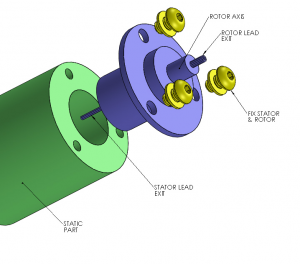
- Flanged slip rings (M1 and M2 styles) are designed to be mounted with screws and washers as shown in Figure 1 below. The washers protect the flange against excessive forces. If lock washers are used, flat washers should be mounted between the lock washer and the flange.
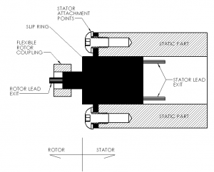
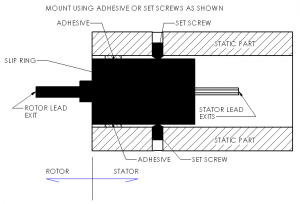
- Slip rings without flanges (M3 style) should also be mounted by securing the stator. This is most commonly done by inserting the body of the slip ring into a hole that is slightly larger than the OD and then securing it as shown in Figure 2. The most common methods include set screws, adhesives, or O-rings.
- The rotor should be driven with a flexible drive coupling to accommodate any differences in the assembly and slip ring’s axis of rotation. Rubber tubing, heat shrink tubing, or a flexible coupling can be used. For applications that run at 5 rpm or less, the rotor leads can be used as the flexible coupling. See Figure 2.
- The slip ring’s bearings are not designed to support external or radial loads. The rotating parts should be supported in such a way that axial and radial forces applied to the slip ring bearings are minimized.
- The slip ring should be protected from dust and moisture. If installed in an outdoor application, the slip ring should be designed to operate in a weather-proof enclosure.
- Secure the leads so that they do not contact any surface of the equipment as it rotates.While routing the wires, do not allow the leads to apply any side loading to the slip ring.
Please contact us with any questions you have about capsule slip rings.
Through Hole Slip Ring Installation Guide
Proper Use and Mounting Instructions
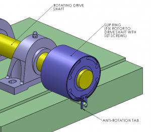
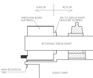
- The through-bore slip ring is designed to be mounted rigidly to the rotating drive rod with the body floating. The slip ring’s inner bore should be slightly larger than the diameter of the drive rod for the application. A slip fit over the drive shaft is needed at a minimum. Bushings can be used to match shaft diameters that are in between the standard thru bore diameters.
- The rotor is secured to the rotating driveshaft that runs through the middle of the slip ring with set screws located on the slip ring’s rotor. The anti-rotation tab (See Figure 1 and 2) should be fitted loosely over a stationary dowel to keep the body from rotating. Other than rotation, it should be free to move slightly based on variances in the alignment.
- The slip ring is NOT designed to bear the assembly.weight of the equipment to which it is connected. Rotating equipment should be supported so that axial and radial forces applied to the slip ring bearings are minimized.
- Because of possible variances, “hard mounting” of both ends of the slip ring (ie. securing the rotor and stator such that there is NO compliance during operation) is not recommended and may cause premature failure.
- The slip ring should be protected from dust and moisture. If installed in an outdoor application, the slip ring should be designed to operate in a weather-proof enclosure.
- Secure the leads so that they do not contact any surface of the equipment as it rotates.While routing the wires, do not allow the leads to apply any side loading to the slip ring.
Please contact us with any questions you have about through-bore slip rings.